This product is suitable for AC rated voltage 35kV and below lines for power transmission and distribution. It is commonly used in urban underground power grids, power station lead lines, internal power supply of industrial and mining enterprises, and underwater transmission lines across rivers and seas.
Implementation standards
This product complies with GB/T12706 "Extruded Insulated Power Cables with Rated Voltages of 1kV (Um=1.2kV) to 35kV (Um=40.5kV)", GB/T12706.2 Part 2: Rated Voltages of 6kV (Um=7.2kV) to 30kV (Um=36kV) and GB/T12706.3 Part 3: Rated Voltage of 35kV (Um=40.5kV)
Usage Features
1.The allowable long-term operating temperature of the cable conductor is:
Maximum conductor temperature of various insulation compound cables (GB/T12706.2 Part 2)

|
Insulation mixture |
Maximum conductor temperature ℃ |
|
|
Normal operation |
Short circuit (lasts up to 5 seconds) |
|
|
Polyvinyl chloride (PVC/A) Conductor cross-sectional area ≤ 300 mm² Conductor cross-sectional area > 300 mm² Cross-linked polyethylene (XLPE) |
70 |
160 |
Maximum conductor temperature of XLPE insulation compound cable (GB/T12706.3 Part 3)
|
Insulation mixture |
Maximum conductor temperature ℃ |
|
|
Normal operation |
Short circuit (lasts up to 5 seconds) |
|
|
Cross-linked polyethylene (XLPE) |
90 |
250 |
2.The ambient temperature during cable laying must not be lower than 0°C;
3.Minimum bending radius allowed when laying cables:
|
project |
Single-core cable |
Multi-core cable |
||
|
Minimum bending radius of the cable during installation |
No armor |
Armored |
No armor |
Armored |
|
20D |
15D |
15D |
12D |
|
|
Note: D is the outer diameter of the cable |
||||
4.Rated voltage
The power frequency rated voltage U0/U (Um) of the second part of GB/T12706.2 cables is 3.6/6 (7.2) kV, 6/6 (7.2) kV, 6/10 (12) kV, 8.7/10 (12) kV, 8.7/15 (17.5) kV, 12/20 (24) kV, 18/30 (36) kV。
GB/T12706.3 Part 3: The power frequency rated voltage U0/U (Um) of the cable is 21/35 (40.5) kV and 26/35 (40.5) kV。
U0:Rated power frequency voltage between the conductor and the ground or the metal shield for cable design;
U:Rated power frequency voltage between conductors for cable design;
Um:The maximum value of the "maximum system voltage" that the device can withstand。
Routine test
|
Rated voltage U0 (kV) |
6 |
8.7 |
12 |
18 |
21 |
26 |
|
Test voltage U (kV) |
21 |
30.5 |
42 |
63 |
73.5 |
91 |
|
Duration (min) |
5 |
5 |
5 |
5 |
5 |
5 |
Partial discharge should be in accordance with the provisions of GB/T3048.12-2007. When the voltage is 1.73 U0, there is no partial discharge. The 5-minute voltage testInsulation test without breakdown。
The performance of flame-retardant, halogen-free and low-smoke cables complies with the requirements of GB/T19666-2019 and GB/T18380-2008.
Common cable models
|
model |
name |
|
|
copper core |
Aluminum core |
|
|
YJV |
YJLV |
Cross-linked polyethylene insulated PVC sheathed power cable Cross-linked polyethylene insulated PE or polyolefin sheathed power cable Cross-linked polyethylene insulated steel tape armored PVC sheathed power cable Cross-linked polyethylene insulated steel tape armored PE or polyolefin sheathed power cable Cross-linked polyethylene insulated fine round steel wire armored PVC sheathed power cable Cross-linked polyethylene insulated fine round steel wire armored PE or polyolefin sheathed power cable |
|
The models in the table do not include flame retardant properties |
||
The performance of flame-retardant, halogen-free and low-smoke cables complies with GB/T19666-2019 and GB/T18380-2008 regulations。
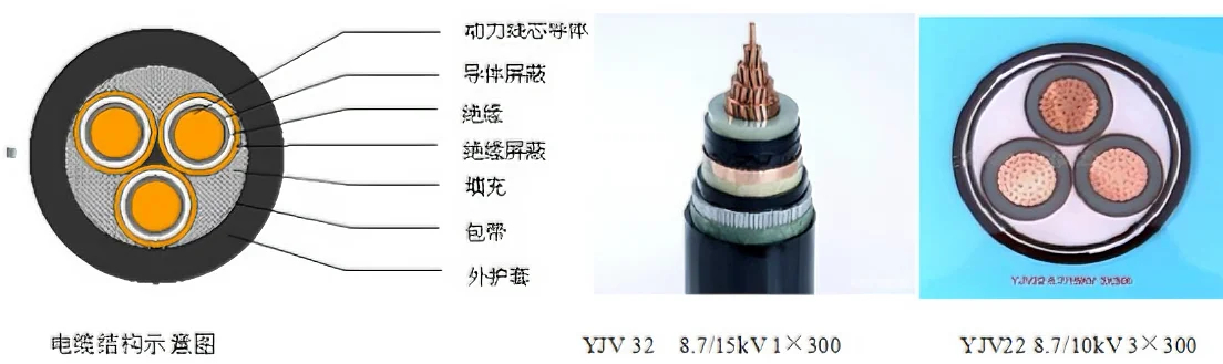
Cable structure diagram and actual
picture